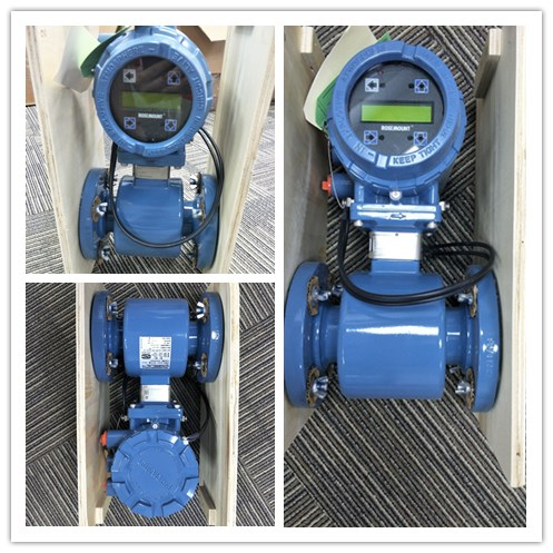

Rosemount 8750W Magnetic Flowmeter
Installation of the Rosemount Magnetic Flowmeter Transmitter includes both
detailed mechanical and electrical installation procedures.
Before installing the Rosemount 8750W, there are several pre-installation steps
that should be completed to make the installation process easier:
1.Identify the options and configurations that apply to your application.
2.Set the hardware switches if necessary.
3.Consider mechanical, electrical, and environmental requirements.
Rosemount 8750W Magnetic Flowmeter
Identify options and configurations
The typical installation of the Rosemount 8750W includes a device power
connection, a 4–20mA output connection, and sensor coil and electrode
connections. Other applications may require one or more of the following
configurations or options:
Pulse output
Rosemount 8750W Magnetic Flowmeter
Discrete input/discrete output
HART Multidrop Configuration
Hardware switches
The Rosemount 8750W electronics stack is equipped with user-selectable
hardware switches. These switches set the Alarm mode, Internal/external analog
power, Internal/external pulse power(1), and Transmitter security. The standard
configuration for these switches when shipped from the factory are as follows:
Rosemount 8750W Magnetic Flowmeter
Wiring the transmitter
This wiring section covers the wiring between the transmitter and sensor, the
4–20mA output, and supplying power to the transmitter. Follow the conduit
information, cable requirements, and disconnect requirements in the sections
below.
For sensor wiring diagrams, see Electrical Drawing 8750W-1504.
See Installation Drawing 8750W-1052.
Rosemount 8750W Magnetic Flowmeter